Switches and Relays


Switches
We have learned how electrons flow through a circuit, now it is time to learn how to control them. The switch is simply a method of disconnecting part of the circuit path on order to stop and start the flow of electricity. When you close the contacts of the switch you "MAKE" the circuit, and when you open the contacts you "BREAK" the circuit. Switches can have many forms, shapes and functions.
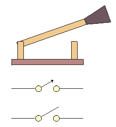
A SIMPLE KNIFE SWITCH
( SPST )
Move your mouse over the image.
This is a simple knife switch. When the user places the knife lever into the lower contact, electrical energy can flow from the wire on the left to the wire on the right. While this type of switch is not commonly used today, it is useful for the purpose of showing the basic operation of most switches. Switches can have multiple contacts so that they can switch more than one circuit at a time, or then can switch between multiple circuits.

The switch in the circuit above has a single contact or POLE that can start or stop the electrical flow. You can only THROW the switch ON (closed contact) or OFF (open contact). This is called a Single Pole Single Throw switch, or SPST for short. 
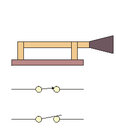
A DOUBLE KNIFE SWITCH
( DPST )
Move your mouse over the image.
This is a variation on the knife switch above. If you notice, it has two poles that you can throw to start (turn ON) and stop (turn OFF) two circuits at the same time. It is said that this switch has Double Poles, and a Single Throw. This switch is known as a DPST switch.

Even though a switch may not look like the knife switch, it will function basically the same. It would be too involved to draw a picture of a switch like the ones above every time you wanted to show a circuit layout. Engineers have designed a set of schematic symbols to represent components used in electronics. Below you will find the schematic diagrams for several different type switches.
SWITCH TYPES AND NOMENCLATURE
This is a Single Pole Single Throw ( SPST ) switch in the OPEN or OFF position.
This is the same SPST switch in the CLOSED or ON position.
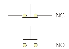
This is also a SPST switch even though it appears different. This is a momentary push button. The upper example is a Normally Closed ( N.C. ) switch while the one below is a Normally Open ( N.O. ) switch.

The NC switch will be in the ON position until you press it, then the circuit opens until you remove your finger. The N.O. switch will be in the OFF position until you press it, then it will remain ON until you release it. A common example of the N.O. Momentary switch is your doorbell button.

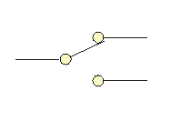
This is a Single Pole Double Throw ( SPDT ) switch. It can connect the point on the left to either position #1 (top) or position #2 (bottom). This could be useful in switching between two lamps, selecting high or low power, or other possibilities.
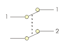
This diagram looks very much like two SPST switches because it is exactly that. Two SPST switches are joined by a non-conductive material so that they both open and close at the same time. This is the symbol for the DPDT switch as shown in the DPDT Knife Switch above.
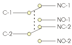
This rather complex switch is a DPDT or Double Pole Double Throw switch. It can select between two positions and select two circuits at the same time. This is a very useful switch in robotics for switching direction on electric motors. It also has many other uses.
RELAYS
This is an interesting device, it is called a reed switch. One lead is made of a non-magnetic material, the other is made of a magnetic material. When a magnet is brought near the device, the reeds make contact and the switch closes. ( Turns ON. ) The reed switch is often used in burglar alarms to detect unwanted entry into a building. The reed switch is placed on the door frame while the magnet is attached to the door. When the door is opened, the circuit breaks and an alarm will sound. Reed switches are available in N.O. and N.C. configurations.

If a coil of wire has an electric current passing through it, it will give off a magnetic field. If this coil is wrapped around a ferrite core ( containing iron ) it will become a temporary magnet. When a temporary or electromagnet is combined with a reed switch, it is called a reed relay. This is a device that will allow you to use an electric current to control another electronic circuit. 

If more current carrying ability is needed, the contacts if a switch are connected to an armature. This armature is pulled in when electric current is applied to a coil. A spring will return the contacts to the open position upon the removal of electricity to the coil. 

This diagram shows a simple SPST relay. The reed relay mentioned above would share this same symbol as it operates exactly the same way electrically.

Here you can see that it is possible to have a SPDT configuration as well. With no current applied to the coil, the input of the common ( C ) connector is routed to the N.C. output of the relay. When current is supplied to the coil of the relay, it pulls in and connects the common ( C ) connector to the N.O. connector. 

It is possible to have many combinations of switches built into a relay. If you had four SPST switches built into a single case, it would be called a 4PST switch for example.